ESP8266 with Arduino - Trials and Errors
ESP8266 is a popular WiFi module for its extremely affordable price. However, more errors tend to be encountered during the setup of this primitive module.
In this tutorial, the basic steps of setting up ESP8266 through an Arduino board would be covered, and some personal trials and errors will be shared in hope to save people's time and life if they are stuck with the same problems as I did.
I am actually an Arduino beginner and a software person. But in turn, I faced more errors than others, managed to solved them, and have more to share with other people who are also new to Arduino and ESP8266 WiFi module!
Introduction & Setup
What is ESP8266?
An extremely affordable hardware component ($USD 3) to connect to WiFi.
Comes with a variety of different models, which are all based on the same chip. The most popular model is ESP-03, which is of similar price to ESP-01 that I will be using in this tutorial, but with more ports (so regretful, should have picked this one).

Components
- ESP8266 WiFi module ESP-01 (or other)
- Arduino Mega board (or others)
- Logic level converter (optional)
- Breadboard, wires, ...
- Arduino IDE (optional)
Before You Start...
- If you don't know what AT command is, DON'T SKIP THE SECTION INTRODUCING IT. I'll make it simple, I promise, but don't directly dive into writing the codes before you know the basics of AT commands, like I did - you'll end up wasting more time dealing with errors.
- Always start with the most basic examples.
- Just to let you know, Arduino is not necessary for you to program ESP8266. Interestingly, more tutorials I found online deal with it with a USB to serial converter such as the FTDI232R module. Follow this tutorial if you have an Arduino board with you, or else you can follow the nice tutorials I took reference on in the reference list.
- Arduino IDE is also not mandatory, there are other ways to write program and upload to ESP8266. But I didn't do research on it, as that is not my intention for my project.
- Setting up a bare ESP8266 module without other assisting development board is FRUSTRATING. If you don't have as much confidence as I did and are just finding a quick way to hack it out for assignments without budget concerns, then go ahead and buy any of those development borads and make your life easier.
Getting Started!
- Hooking up ESP8266 + Sending AT Commands
- Programing ESP8266
- Examples
- Client Example - Programming ESP8266 Like Arduino
- Client Example - Talking to ESP8266 via Arduino
- Server Example - Programming ESP8266 Like Arduino
- Server Example - Talking to ESP8266 via Arduino
1. Hooking Up ESP8266 + Sending AT Commands
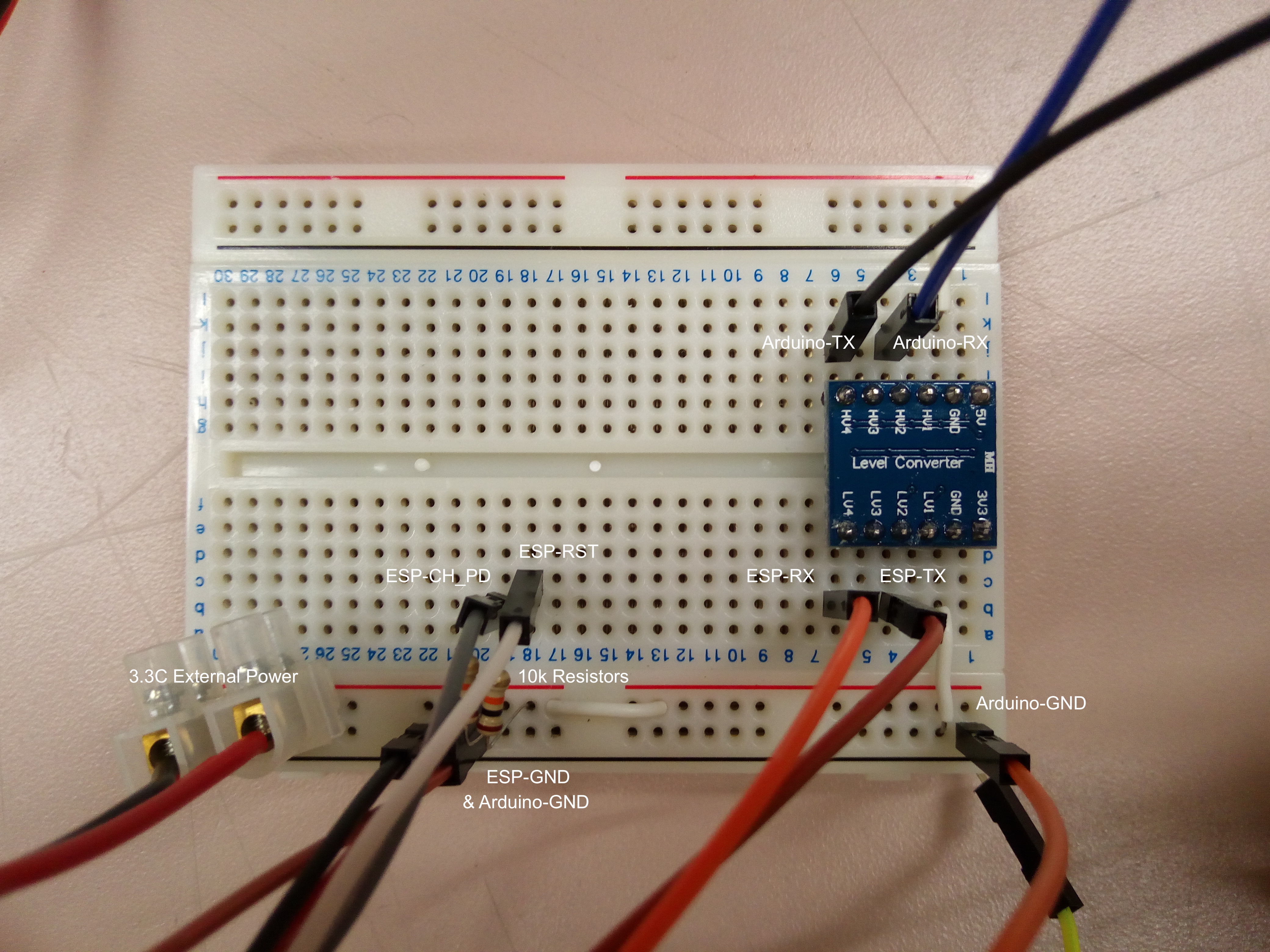
Here are the pins for ESP-01 model:
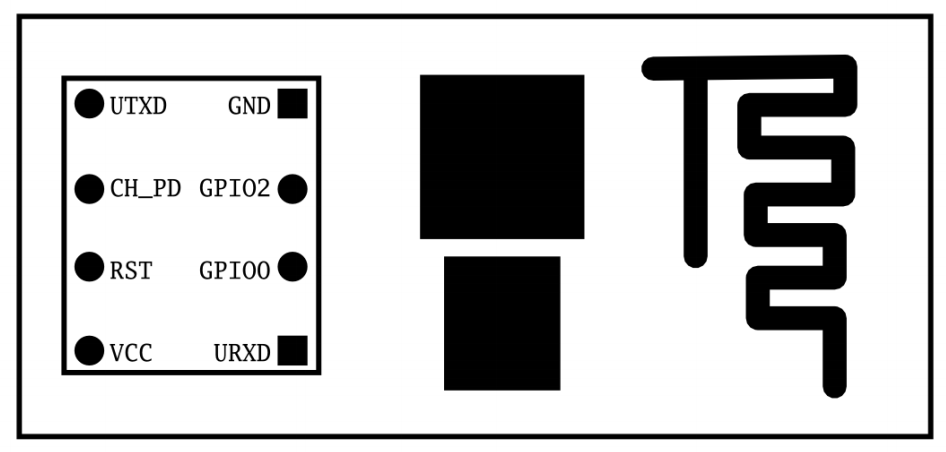
Connections
| ESP8266 | Arduino | Others | Purpose |
|---|---|---|---|
| Vcc | - | 3.3V | Power supply |
| GND | GND | GND | Ground |
| URXD | Rx / Tx | - | Receive data in |
| UTXD | Tx / Rx | - | Transmit data out |
| CH_PD | - | Normally 3.3V | Chip power down |
| RST | - | 3.3V for normal operations / GND for reset | Reset |
| GPIO0 | - | - for normal operations / GND for flashing firmware | General purpose I/O pins, but used in flashing firmware |
| GPIO2 | - | - | General purpose I/O pin |
Key Notes
- NEVER connect Vcc and other pins to 5V.
- ESP8266 operates on 3.3V; connecting pins to 5V may damage the module.
- For Rx/Tx pins, the one receiving data through Arduino board should theoretically also be logically shifted down to 3.3V; but many people didn't encounter problem connecting them directly to each other's pins, including me.
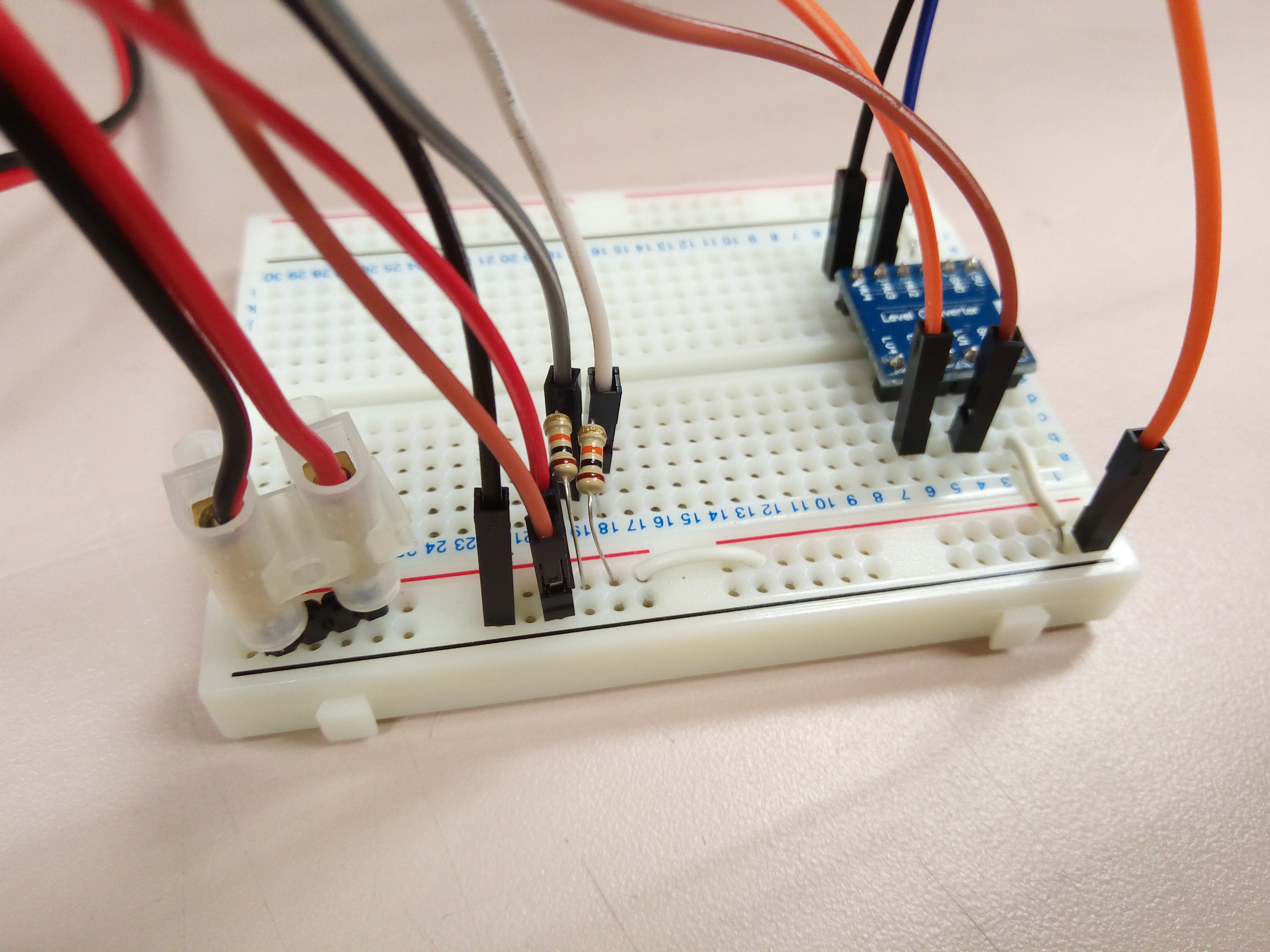
- DON'T connect 3.3V power pin of Arduino to ESP8266. Use a logic level converter to bring 5V down to 3.3V.
- The max limit of current flowing out of that pin is around 50 mA, which usually is not enough. That's why we need a logic level converter; there are other ways to bring 5V down to 3.3V, but using logic level converter ensures a better transmission performance. You can also connect it to external power source, which should be the best way to ensure stability.
- Rx-Rx, Tx-Tx: uploading program from computer to ESP8266 via Arduino board; Rx-Tx, Tx-Rx: letting Arduino board talk to ESP8266.
- Think of Rx-Rx, Tx-Tx as making Arduino board a channel between the computer and ESP8266; whatever goes to the Arduino board goes to ESP8266, and whatever ESP8266 sends back goes to the computer.
- Think of Rx-Tx, Tx-Rx as making Arduino talk to ESP8266, so probably you would have some program in Arduino sending and receiving data/commands via its own serial ports.
- I don't know what CH_PD port does. Normally just leave it at 3.3V.
- If thinking of ESP8266 as an Arduino board, then Rx, Tx, GPIO0, and GPIO2 are the possible digital pins, where Rx/Tx are the predefined Serial ports.
- If you are programming directly into ESP8266, then when using up Rx and Tx, you would probably find yourself out of Serial ports for debugging. I'm not sure how it can be solved, but probably you can set GPIO2 as the TX pin for debugging or extend your ports. Not sure if they make sense for ESP-01 model (try it and tell me).
- Learn more on GPIO ports
Basics of AT Commands
If you have experience using terminals, then AT commands are of the same concept as those commands you put into the terminal. In terminal, when you input ls and send, some programs would be run, then some outputs would be sent back to your terminal window and shown. You interact via the terminal with your computer software with a set of commands available.
Similarly, you interact via the serial monitor with your ESP8266 with a set of AT commands available.
Simple, isn't it? Instead of guiding you through how to send the various AT commands, I'll only use 2 AT commands to test the module in the following section - AT and AT+GMR. You should try more yourself looking at this doc, including how to scan for available WiFis and connect to them via AT commands, but I do not tend to terrify you with a bunch of those commands, as they are not needed if you are using libraries that wraps up those commands for you.
But knowing how this mechanism drives the interaction with ESP8266 is essential in effective comprehension of the libraries used in the following sections.
Testing with Andruino IDE
Connection: Rx-Rx, Tx-Tx, RST-3.3V, GPIO0 & GPIO2 floating.
Note that you are directly talking to ESP8266 via Arduino board as a channel.
- Connect and power up your Arduino board & ESP8266
- Make sure you Arduino board isn't loaded with other programs. Either reset your Arduino baord, or upload a
BareMinimumexample program to it - Open up Arduino IDE, select
Tools > Port > YourConnectedPort - Open up
Serial Monitor, and listen to baudrate115200. You may see some messages bump up; those should be from ESP8266. Recognize thereadymessage at the end. See image in step 7- Try other baudrates if you are seeing random symbols, or seeing nothing
- Select
Both NL & CRoption - it adds\r\nafter your input line. Necessary for sending a valid AT command - Input
ATin your input box and pressenter. You should see the responseOKfrom ESP8266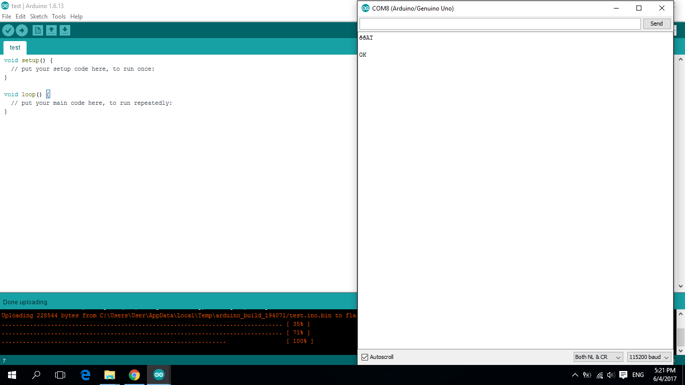
- Input
AT+GMRin your input box and pressenter. You should see the version information of your ESP8266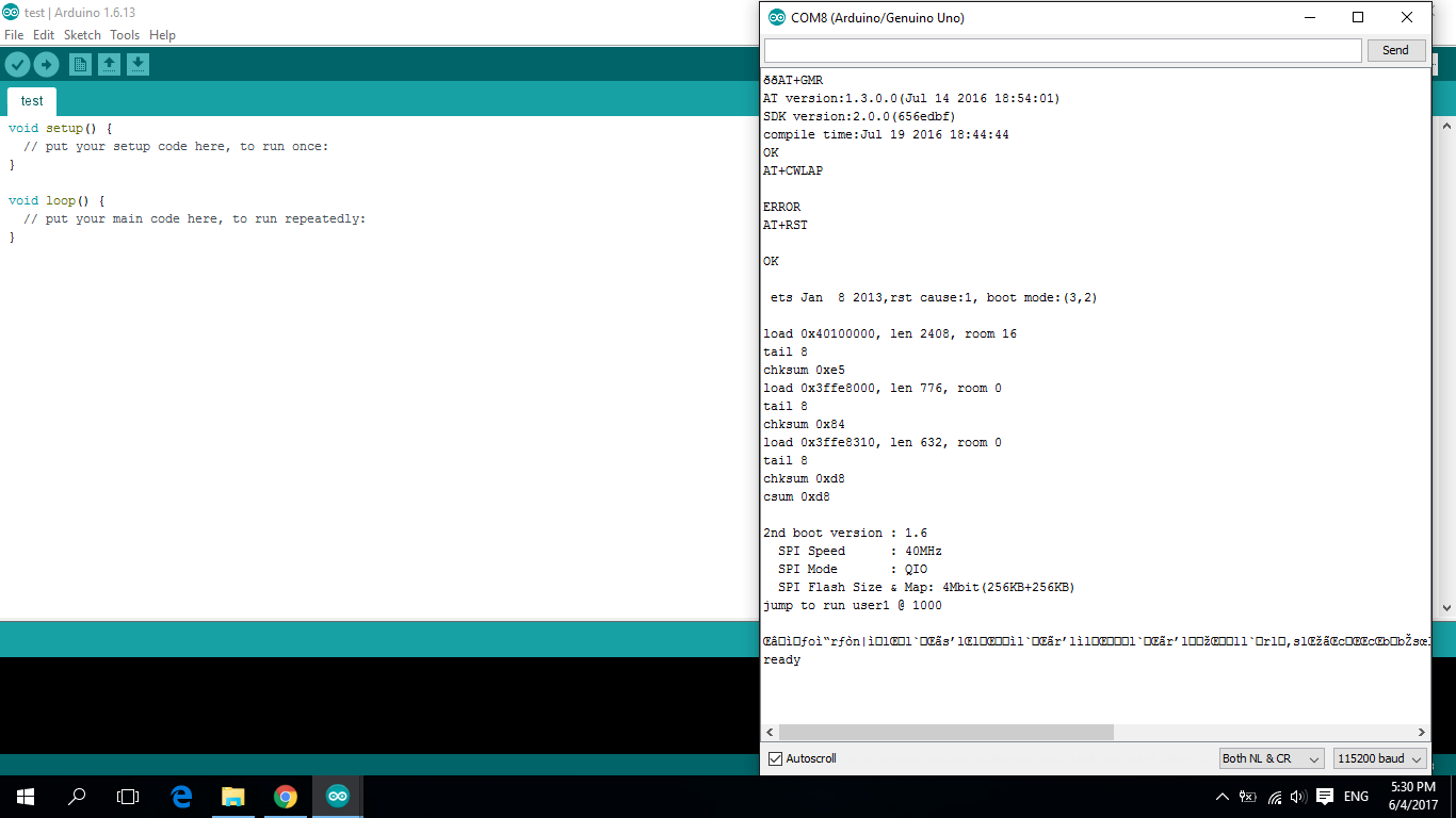
If everything shown is as expected, congratulations, your ESP8266 is working, and you can move on to the programming section. If not, then go to the troubleshooting section for help.
Alternative1: Testing with PuTTY on Windows
Connection: Rx-Rx, Tx-Tx, RST-3.3V, GPIO0 & GPIO2 floating.
Note that you are directly talking to ESP8266 via Arduino board as a channel.
- Connect and power up your Arduino board & ESP8266
- Make sure you Arduino board isn't loaded with other programs. Either reset your Arduino baord, or upload a
BareMinimumexample program to it if so - Check the serial port number of your device under
Device Manager > Ports > USB Serial PortorArduino IDE > Tools > Port - Open up PuTTY, select
Connection type > Serial, inputSerial line > COMXwhereCOMXis your connected serial port number,Speed > 115200or other baudrates that work. PressOpen. Some messages bump up as in Arduino IDE - Enter
AT, hold downCtrlkey, pressmkey, pressjkey, releaseCtrlkey. This sends anATcommand ending with\r\n. You should see the responseOK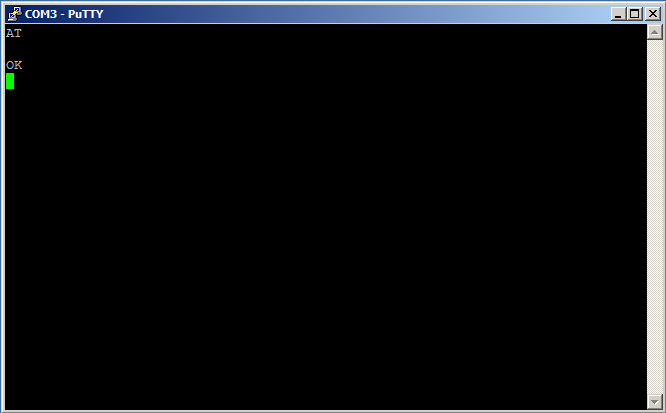
- Enter
AT+GMRand do the same thing as above. You should see the version information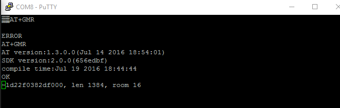
Alternative2: Testing with Arduino Board
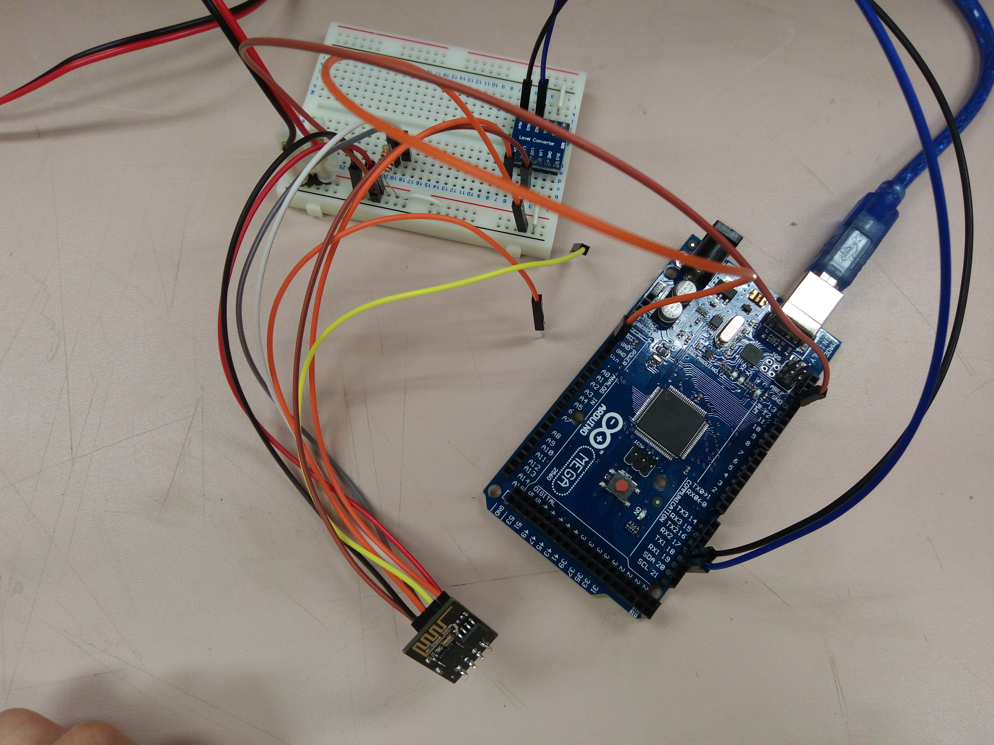
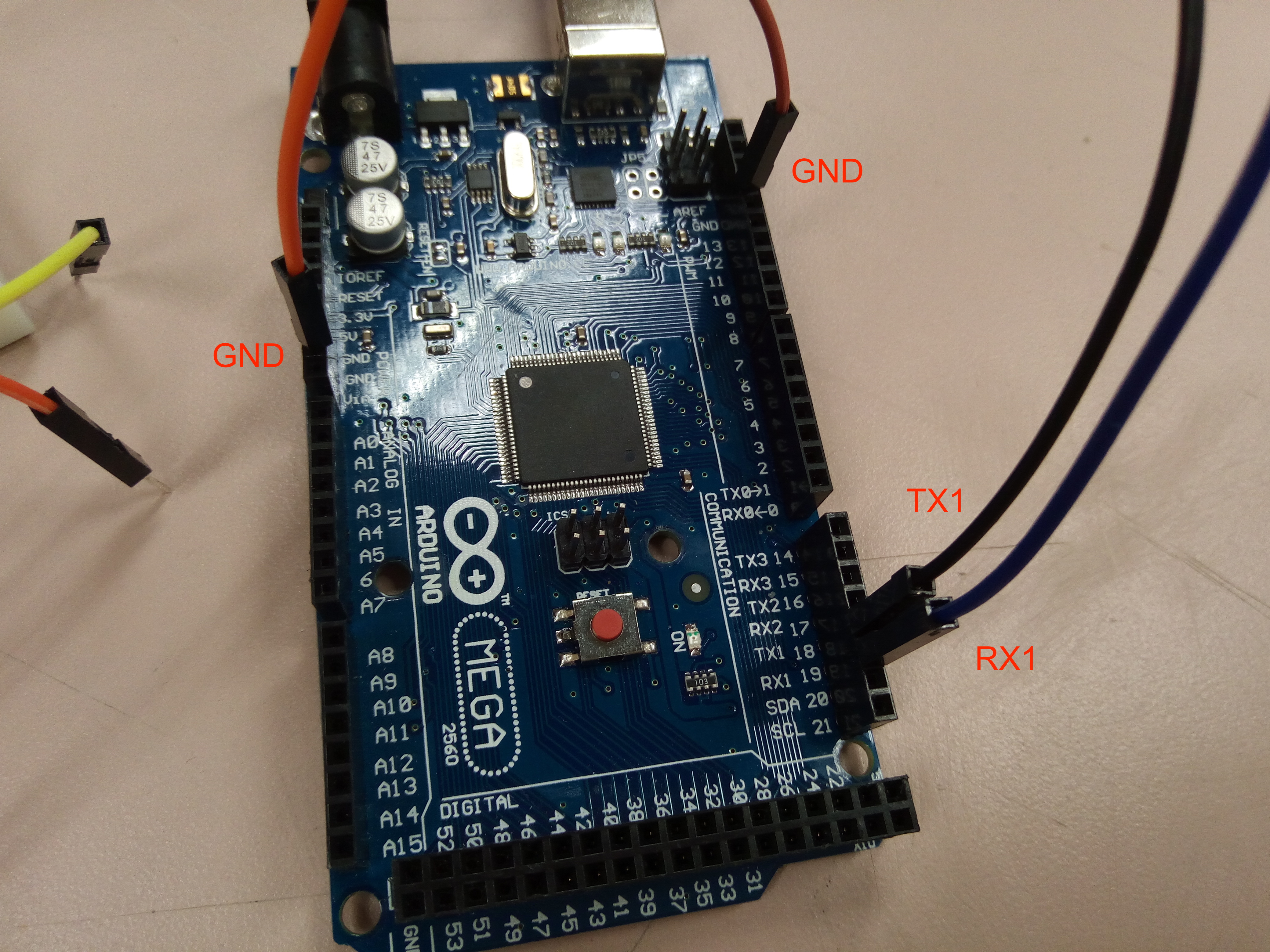
Connection: Rx-Tx1, Tx-Rx1, RST-3.3V, GPIO0 & GPIO2 floating for Mega; Rx-D2, Tx-D3, RST-3.3V, GPIO0 & GPIO2 floating for Uno.
Note that your Arduino board is the one talking to ESP8266.
- Connect and power up your Arduino board & ESP8266
Open up a new Arduino
BareMinimumexample, copy and paste the following code:// For boards with more than 1 hardware serial ports e.g. Mega void setup() { Serial.begin(115200); // Debug message talking on baudrate 115200 Serial1.begin(115200); // ESP talking on baudrate 115200 } void loop() { if (Serial1.available()) { // ESP wants to talk to you Serial.write(Serial1.read()); // Log out what ESP wants to say } if (Serial.available()) { // You want to talk to ESP (you input and send something via the input field) char chars = Serial.read(); // Read 1 byte (1 char) at a time Serial1.write(chars); // Tell ESP your words/commands 1 byte (1 char) at a time } }Serialis for logging your debug message;Serial1is theTx1/Rx2pair which your ESP module is connected to.
// For boards with only 1 hardware serial port e.g. Uno, we have to use SoftwareSerial ports, i.e. take other digital output pins as your serial port #include <SoftwareSerial.h> SoftwareSerial ESP(3, 2); /* RX:D3, TX:D2 */ void setup() { Serial.begin(115200); // Debug message talking on baudrate 115200 ESP.begin(115200); // ESP talking on baudrate 115200 } void loop() { if (ESP.available()) { // ESP wants to talk to you Serial.write(ESP.read()); // Log out what ESP wants to say } if (Serial.available()) { // You want to talk to ESP (you input and send something via the input field) char chars = Serial.read(); // Read 1 byte (1 char) at a time ESP.write(chars); // Tell ESP your words/commands 1 byte (1 char) at a time } }SoftwareSeriallibrary is necessary if you are having only 1 Serial port and you want it to be the debug port.- Try
AT+GMRcommand; if you see the message corrupted, i.e. some parts of the message is somehow not readable, don't assume you're ok. see troubleshooting section.
Select
Tools > Board > YourConnectedArduinoBoard,Tools > Port > YourConnectedPort. Upload the programThe following steps are the same as step 4 ~ step 7 in the main testing method Testing with Andruino IDE
2. Programing ESP8266
There are basically 2 ways of using the ESP8266 module: programming ESP8266 like Arduino and talking to ESP8266 via Arduino. Strictly speaking, the latter one may not really mean to program the module; it is the program we upload into Arduino board that sends commands to ESP8266 on behalf of us.
- Programming ESP8266 like Arduino: directly upload programs to ESP8266 and treat it like Arduino
- Talking to ESP8266 via Arduino: upload program into Arduino board that sends commands to ESP8266 on behalf of us
I didn't notice the different programming methods at first, and follow whatever the first tutorial I found online that is workable, that is to program ESP8266 like Arduino. But later I found that I really need another serial port for communication in addition to the debug port! There are workarounds, as stated in Getting Started! > Hooking Up ESP8266 + Sending AT Commands > Connections > Key Notes in this tutorial, but I was too tired to try so. Then I switched to the other method, in which the debug port is the Mega's.
However, the latter method is less stable then the first one, as errors tend to come out more often with the extra communication between Arduino and ESP. Choose whatever suits your purpose the best.
Programming ESP8266 Like Arduino
Connection: Rx-Rx, Tx-Tx, RST-3.3V, GPIO0 & GPIO2 floating.
Library: esp8266/arduino
- Go through the installation guide
- Open up any examples under
File > Examples > WiFi, for example, theSimpleWebServerWiFi - Replace the
ssidandpasswordwith a reachable WiFi AP at your place- See troubleshooting for the requirements on the AP network
- Change the baudrate to a workable one, in our case,
115200 - Select
Tools > Board > ESP8266 Modules > Generic ESP8266 Module(or others if you're not using bare ESP8266),Tools > Port > YourConnectedPort - Upload the program to ESP
- Diconnect power to ESP
- Bring
GPIO0to ground - Power up ESP
- Pull out
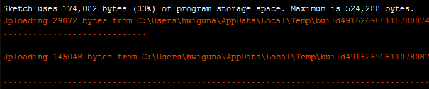
GPIO0to float - Click the upload button in IDE
- You should see something like this:
Talking to ESP8266 via Arduino
Connection: Rx-Tx1, Tx-Rx1, RST-3.3V, GPIO0 & GPIO2 floating.
Library: itead/ITEADLIB_Arduino_WeeESP8266
- Install the library
- Download the library as a
zipfile - Under
Sketch > Include Libaray, selectAdd .ZIP Library... - Choose your downloaded
zipfile
- Download the library as a
- Open up any examples under
File > Examples > ITEADLIB_Arduino_WeeESP8266, for example, theConnectWiFi - Replace the
ssidandpasswordwith a reachable WiFi AP at your place- See troubleshooting for the requirements on the AP network
- Change the baudrate to a workable one, in our case,
115200 - Select
Tools > Board > Arduino AVR Boards > Arduino/Genuino Mega or Mega2560(or others),Tools > Port > YourConnectedPort - Upload the program to Arduino board
- Open up the serial monitor, and you should see messages showing the program interacting with ESP
3. Examples
The examples are modified from the ones included in the libraries, but I'll put more comments in the code.
1. Client Example - Programming ESP8266 Like Arduino
Connection: Rx-Rx, Tx-Tx, RST-3.3V, GPIO0 & GPIO2 floating.
HTTPClient is a wrapper of WiFiWebClient, which is more easy to use. No need to wrap the request message yourself.
Modified from: esp8266/arduino - BasicHttpClient
/* Posting values from 0 to 255 onto dweet.io */

#include <stdio.h>
#include <ESP8266WiFi.h>
#include <ESP8266HTTPClient.h>

#define MAX 255
#define MIN 0

const char* ssid     = "xxx";
const char* password = "xxx";

const char* urlPath = "http://dweet.io/dweet/for/thing-name?value=";                // dweet.io is a simple messaging host for IoT devices
char url[100];

IPAddress ip_static(192,168,137,2);                                                 // Use a static IP address
IPAddress gateway(192,168,137,1);                                                   // Gateway should be the IP of your connected hotspot device
IPAddress subnet(255,255,255,0);                                                    // Check subnet  through that device as well

int value = 0;

void setup() {
  Serial.begin(115200);                                                             // Serial for debug messages, since we're using ESP like Arduino

  // Connect to WiFi network
  WiFi.config(ip_static, gateway, subnet);
  WiFi.begin(ssid, password);
  Serial.print("\n\r \n\rWorking to connect");

  // Wait for connection
  while (WiFi.status() != WL_CONNECTED) {
    delay(500);
    Serial.print(".");
  }
  Serial.println("");
  Serial.print("Connected to ");
  Serial.println(ssid);
  Serial.print("IP address: ");
  Serial.println(WiFi.localIP());
}

void loop() {
  delay(5000);
  if (WiFi.status() == WL_CONNECTED) {
    HTTPClient http;

    // Create URI for the request
    ++value;
    value %= MAX;

    sprintf(url, "%s%d", urlPath, value);

    Serial.print("connecting to ");
    Serial.println(url);

    http.begin(url);                                                                  // TCP handshake with host

    int httpCode = http.GET();                                                        // GET request, return response
    Serial.print("httpCode: ");
    Serial.println(httpCode);
    if (httpCode > 0) {
      String payload = http.getString();
      Serial.println(payload);
    }

    http.end();                                                                        // Close TCP connection
  }
}
2. Client Example - Talking to ESP8266 via Arduino
Connection: Rx-Tx1, Tx-Rx1, RST-3.3V, GPIO0 & GPIO2 floating.
Modified from: ITEADLIB_Arduino_WeeESP8266 - HTTPGET
#include "ESP8266.h"

#define SSID        "xxx"
#define PASSWORD    "xxx"
#define HOST_NAME   "dweet.io"
#define HOST_PORT   (80)

ESP8266 wifi(Serial1, 115200);

void setup(void)
{
    Serial.begin(115200);
    Serial.print("setup begin\r\n");

    Serial.print("FW Version:");
    Serial.println(wifi.getVersion().c_str());

    if (wifi.setOprToStationSoftAP()) {
        Serial.print("to station + softap ok\r\n");
    } else {
        Serial.print("to station + softap err\r\n");
    }

    if (wifi.joinAP(SSID, PASSWORD)) {
        Serial.print("Join AP success\r\n");

        Serial.print("IP:");
        Serial.println( wifi.getLocalIP().c_str());
    } else {
        Serial.print("Join AP failure\r\n");
    }

    if (wifi.disableMUX()) {
        Serial.print("single ok\r\n");
    } else {
        Serial.print("single err\r\n");
    }

    Serial.print("setup end\r\n");
}

void loop(void)
{
    uint8_t buffer[1024] = {0};

    if (wifi.createTCP(HOST_NAME, HOST_PORT)) {
        Serial.print("create tcp ok\r\n");
    } else {
        Serial.print("create tcp err\r\n");
    }

    char *message = "GET /dweet/for/thing-name?value=1 HTTP/1.1\r\nHost: dweet.io\r\nConnection: keep-alive\r\n\r\n";
    wifi.send((const uint8_t*)message, strlen(message));

    uint32_t len = wifi.recv(buffer, sizeof(buffer), 10000);
    if (len > 0) {
        Serial.print("Received:[");
        for(uint32_t i = 0; i < len; i++) {
            Serial.print((char)buffer[i]);
        }
        Serial.print("]\r\n");
    }

    if (wifi.releaseTCP()) {
        Serial.print("release tcp ok\r\n");
    } else {
        Serial.print("release tcp err\r\n");
    }

    delay(5000);
}
3. Server Example - Programming ESP8266 Like Arduino
Connection: Rx-Rx, Tx-Tx, RST-3.3V, GPIO0 & GPIO2 floating.
Modified from: Adafruit - ESP8266 Temperature / Humidity Webserver
#include <ESP8266WiFi.h>
#include <WiFiClient.h>
#include <ESP8266WebServer.h>

const char* ssid     = "xxx";
const char* password = "xxx";

ESP8266WebServer server(80);                                                           // Listening on port 80

String webString="";                                                                   // String to display

void handle_root() {
  server.send(200, "text/plain", "Hello from esp8266!");                               // If accessing root, respond this message
  delay(100);
}

void setup(void)
{
  // You can open the Arduino IDE Serial Monitor window to see what the code is doing
  Serial.begin(115200);

  // Connect to WiFi network
  WiFi.begin(ssid, password);
  Serial.print("\n\r \n\rWorking to connect");

  // Wait for connection
  while (WiFi.status() != WL_CONNECTED) {
    delay(500);
    Serial.print(".");
  }
  Serial.println("");
  Serial.print("Connected to ");
  Serial.println(ssid);
  Serial.print("IP address: ");
  Serial.println(WiFi.localIP());

  server.on("/", handle_root);                                                         // If client requests root page, handle it with handle_root subroutine

  server.on("/test", [](){                                                             // If client requests /test page, handle it with the code section
    webString="Hello World!";
    server.send(200, "text/plain", webString);
  });

  server.begin();
  Serial.println("HTTP server started");
}

void loop(void)
{
  server.handleClient();                                                                // Waiting for clients to connect
}
4. Server Example - Talking to ESP8266 via Arduino
To be released.
Trouble Shooting
1. Hooking Up ESP8266 + Sending AT Commands
Testing with Andruino IDE
- If you do not see
readyas the response message, and you find that you can't send any commands out or receive any responses, your ESP8266 is probably stuck. Try:- Reset: pull GPIO0 to GND, pull RST to GND, pull RST back to Vcc, pull GPIO0 out to floating.
- If not working, power off ESP and power on ESP. Reset again.
- If not working, follow this guide on updating your firmware to the latest version. This is really recommended!!!
- Download the latest Flash Download Tool
- Download the latest ESP8266 SDK. Choose Non-OS SDK.
Testing with Andruino Board
- If you're using Arduino Uno and ESP is sending you responses that doesn't appear readable, the data might be corrupted due to the high baudrate
115200that Arduino Uno cannot withstand, or some voltage level problems. Try:- Ensure every GNDs are connected, including the ESP's and Arduino's GND pins.
- If not working, lower the baudrate.
- If not working, switch to Mega or other boards.
2. Programing ESP8266
Programming ESP8266 Like Arduino
If you don't know what
ssidandpasswordare,ssidis the network name you would see when you want to connect to WiFi in the available WiFi list e.g.eduroam, andpasswordis the password. Note that there's no options forusername, because ESP8266 doesn't accept enterprise protected access points (WPA2_Enterprise)! So you need to have a private AP available. Some common connection points are from:
- Your router
- Your mobile phone hotspot
Your shared hotspot from a computer that is connected to network cables
Under Windows platforms, there is a convenient way to share its network as hotspot:
Open command prompt, run:
netsh wlan show drivers
netsh wlan set hostednetwork mode=allow ssid=your-preferred-name key=your-preferred-password
netsh wlan start hostednetwork
Make sure the network is allowed to be shared
- Press
Windows + rkey, enterncpa.cpl. This opens upNetwork Connectionspanel. - Right-click
Wi-Fi > properties, switch toSharingand check the first checkbox underInternet Connection Sharingthat readsAllow other network users to connect...
- Press
Test hotspot
- Take out your mobile phone, connect to hotspot, and try to go to a website. If everything is fine, then you are good to go.
If you cannot see the uploading progress message, but instead see a lot of mysterious errors such as
espcomm_open failed,espcomm_sync failed, and a whole bunch of other possibilities, try:- Check your port selection is the right one. Check your circuit connections, ensure the
GNDs are connected. - If not working, repeat the upload process as state in step 6.
- If not working, power off ESP and power on ESP. Upload again.
- If not working, unplug your USB and plug in again. Upload again.
- If not working, follow this guide on updating your firmware to the latest version. This is really recommended!!!
- Download the latest Flash Download Tool
- Download the latest ESP8266 SDK. Choose Non-OS SDK.
- Check your port selection is the right one. Check your circuit connections, ensure the
If you're testing as a server, and have no response after you ping the IP address of ESP, try:
- Connect you computer with WiFi under the same network as ESP8266
Talking to ESP8266 via Arduino
If you're using Arduino Uno and ESP is sending you responses that doesn't appear readable, the data might be corrupted due to the high baudrate
115200that Arduino Uno cannot withstand, or some voltage level problems. Try:- Ensure every GNDs are connected, including the ESP's and Arduino's GND pins.
- If not working, lower the baudrate.
- If not working, switch to Mega or other boards.
If you're testing as a server, and have no response after you ping the IP address of ESP, try:
- Connect you computer with WiFi under the same network as ESP8266
Conclusion
So I believe that's all you need to know to successfully setup an ESP8266 module - ok I guess it's pretty much. Now you know how frustrating the process might be setting up this WiFi module for a software person, and how the cheap price comes with a huge cost.
But I believe I was the one who encountered most of the errors people are likely to encounter and managed to solve them somehow, so I hope the troubleshooting part is comprehensive enough to cover all of your problems. To me, every error popped up appeared to have 100 different possible suggested solutions online, and I almost tried all of them to finally identify one possible valid solution, or sometimes even none of them are valid. I have to say, ESP8266 still have its long way to go.
Finally, I really have to thank the people who wrote the tutorials, instructables, guides, and documentations online, which are mostly included in the following references (cannot put them all).
I will post the sample codes up to GitHub along with a summary of this tutorial as a cheatsheet later if I find time.
References
I bet I've searched through 100 webpages along my journey on setting up ESP8266 without an error. The * starred * ones are the recommended ones that really helped me a lot along my way. Others are more or less the same, but I also took reference on.
- Setting up ESP8266 via USB/TTL converter
- * ESP8266 Wi Fi Module Explain and Connection
- ESP8266 WiFi Module Quick Start Guide
- Getting Started with ESP8266
- Breadboard and Program an ESP-01 Circuit with the Arduino IDE
- How to Install the ESP8266 Board in Arduino IDE
- Installing and Building an Arduino Sketch for the $5 ESP8266 Microcontroller
- Serial-to-WiFi Tutorial using ESP8266
- Programming ESP8266 like Arduino
- * ESP8266 Temperature / Humidity Webserver
- A little bit outdated on IDE setup, but the program uploading steps saved my life!
- * ESP8266 - Easiest way to program so far (Using Arduino IDE)
- ESP8266-01 using Arduino IDE
- ESP8266 ARDUINO TUTORIAL – WIFI MODULE COMPLETE REVIEW
- * ESP8266 Temperature / Humidity Webserver
- Talking to ESP8266 via Arduino
- Connecting your Arduino to WiFi via an ESP-8266 module
- Beginner's Guide to ESP8266 and Tweeting Using ESP8266
- Note that the author said the connection of Rx/Tx depends on the version of ESP8266. Sorry but I doubt that.
- Other nice and comprehensive tutorials
- * 深入淺出 Wifi 晶片 ESP8266 with Arduino Chinese (台灣人好棒棒)
- * Update the Firmware in Your ESP8266 Wi-Fi Module
- Other examples
- Documentations